May 2017 to August 8, 2017

When we left toward Florida in the fall of ’16 the engine had just been mounted. The weather was getting cold. I was OK with the heated hangar but I would be batching it if I didn’t follow Dolly South. Besides, all I had to do was hookup a few hoses and wires.
Hah!! Little did I know.
May 2017
May was all firewall forward work. It included:
- Installing the oil filler neck
- Installing NGK BR8ES 3961 spark plugs gapped to 0.31”
- Installing the exhaust pipes lubed with Mouse Milk
- Installing the cabin heat muff on the #1 cylinder exhaust pipe
- Installing vibration dampers on the exhaust stacks
- Mounting the throttle servo body to the engine
- Fabricating mounts and installing the throttle, mixture and other controls required drilling the firewall and making up cable fittings and linkages to the engine
- Installing fuel lines from the engine pump to the fuel servo, and on to the fuel divider
- Installing an overflow line from the engine fuel pump
- Installing a multi-pressure manifold on the firewall
- Drilling exhaust stacks and installing four Exhaust Gas Temperature sensors
- Installing fire sleeve in several places
- Installing four Cylinder Head Temperature sensors
- Installing a Red Cube fuel flow sensor in the fuel servo to fuel divider line
- Installing SCAT tubing from the heat muff to the firewall heater box

Heater Muff, SCAT tubing, and fuel servo with Red Cube fuel flow sensor under fire sleeve

- Installing fuel, oil and manifold pressure lines and sensors
- Installing a voltage regulator for the backup alternator
- Forming and installing the crankcase breather tube with “whistle slot”
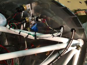
- Threading and lacing the wire bundle going to the Garmin GE24 engine sensor box
- Routing the lower spark plug leads from PMags to cylinders.
May was a busy month of 5-8 hour days in the hangar.
June 2017
I took June 1st off to do EAA Chapter 77 treasury work. After that the month included:
- Mounting the primary alternator and wiring the field and ground lines back through the firewall
- Fabricating buss bars, mounting ANL fuse blocks on the lower right firewall and connecting shunts to the Garmin GE24 amperage sensor inputs.

- Installing an alternator fail light for the main alternator.
- Cutting and fitting nine high amperage cables for the alternators, battery and starter.
- Installing IN5407 diode spark suppression jumpers for the Master and Starter solenoid coils.
- Installing a starter “kill switch” hidden below the instrument panel
- Drilling a 1″ dia. hole in the rear wing spar IAW Van’s instructions to pass the magnetometer plug
- Lacing spark plug wires with wire ties to keep the wires separated
- Testing electrical system components including a starter switch green light and annunciator panel

Green Starter Switch Light turns off when engine runs. - Fabricating a small shelf for Mounting a terminal strip under the PAX seat. The lighting control switches were the first connections to these terminals.
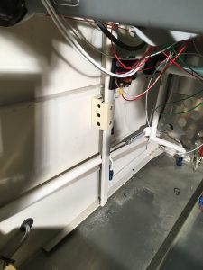
- Running various wires from the instrument panel to junction strips below the Pilot and PAX seats. The pitch and roll servo cables traverse the right side vertical channel. The Magnetometer cable is in the left side channel. All wires were eventually bundled in corrugated flex tubes; some covered with “snake skin”.

Left Wiring Channel

- Fabricating Pilot and PAX headset socket brackets and mounting them on the sides below the instrument sub-panel.
- Installing the Emergency Locator Transmitter on the tunnel cover in front of the seats. The ELT antenna was mounted on a shelf behind the PAX seat. Lithium batteries having a 10 year life were installed in the ELT and the panel mounted alarm. They should be replaced before July 2027.
July 2017
The daily work continued and I
- Removed the front crankshaft expansion plug and pierced the rear plug. Then, I installed a new front plug per Lycoming Service Bulletin No. 1435, converting the engine to fixed pitch operation.
- Fabricated a firewall shelf for mounting the Garmin GPS antenna under the fiberglass cowl.
- Installed the Comm Radio antenna under the plane and on the fuselage center line
- Installed a blade antenna under the pilot seat for the Garmin GDL-39R ADSB receiver
- Installed another blade antenna under the PAX seat for GTX23ES transponder. RG400 coax cable was used for all antennae.
- Mounted the flywheel and a 2-1/4″ Saber Engineering crankshaft extension to the engine, torquing the combination to 50 ft-lbs with Locktite 248
- Installed the Comm Radio, GPS Nav, PFD & MFD EFIS, and TPX in the aircraft and began testing
- Fit the front, side and back baffles to the engine.
- Dolly and I attended the week long Oshkosh EAA Airventure 2017. There we learned of Lycoming Service Bulletin No. 632. Our engine serial number was included in the list of ~1300 that left the factory with potentially insecure connecting rod upper bearings.
August 1 through 8, 2017
Arriving back in Michigan I ordered the tool required to do the S/B #632 inspection. It was back-ordered. Continuing with the build, I
- Calibrated ADHRS #1 and #2 pitch & roll servo offsets and ran many Garmin G3X post-install tests. The left screen in the photo shows when I stumbled onto the Garmin G3X Touch Engineering Test Screen that is not normally available to the customer.
- Installed pitot/AOA tubes and wires.
Then came the day we had long awaited – the plane was ready to receive its wings!


