Let’s build a Vertical Stabilizer

11/28/14                                                                                                                                  

I have an old (3 megapixel) Olympus camera that is now dedicated to recording the build.  I keep it in the tool chest for photos such as these.

OLYMPUS DIGITAL CAMERA

In building the Vertical Stabilizer, the first task is to smooth all edges and slightly round the corners of all the parts.
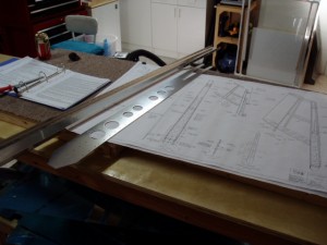
Vertical Stabilizer rear spar and reinforcing plate.


OLYMPUS DIGITAL CAMERA

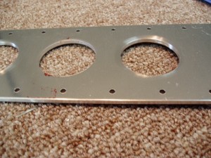
The lightening holes in the reinforcing plate are punched at the factory and have rough edges, as on the center hole shown in the photo on the right.  The other two shiny holes have been finished with a Scotchbrite wheel on a drill and then a hand held Scotchbrite red pad.

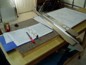


OLYMPUS DIGITAL CAMERA  The ribs have been edge smoothed and their flanges fluted as necessary to straighten any curvature along the length of the rib face.  In preparation for adding the skin, the ribs and spars are Clicoed to form a temporary skeleton structure.


OLYMPUS DIGITAL CAMERAWhen the skin is added, a Clico is placed in every third or forth hole.

Rivet holes in the skin and rib flanges are drilled undersize at the factory.

The next step for the builder is to match drill the holes in the skin to the holes in the spars and rib flanges.  As work progresses, Clicos are moved from undrilled to match drilled holes until all of the several hundred holes are done.


OLYMPUS DIGITAL CAMERA
Dolly is using a three point deburring cutter in a slow speed electric screwdriver. A quick pulse of the trigger is all that is needed.

11/29/14  


Drilling leaves very small but rough burrs on the edges of the holes, particularly where the drill bit has exited the back of the work.  Both sides of each hole on each piece of aluminum must be deburred.


11/30 – 12/01/14  

Like the remainder of an RV’s skin, the vertical stab skin is held to the sub structure with flush rivets.  These rivets require a dimpled or countersunk depression in which to rest their heads (anthropomorphism intended).  Today the VS skin and the lower portion of the VS rear spar were dimpled using an Avery dimpling press.  Rib flange holes matching the skin were dimpled with a hand squeezer.  The lower portion of the thicker rear spar doubler was countersunk.  All parts were then primed in SEM grey primer.

12/02 – 12/03/14  OLYMPUS DIGITAL CAMERA Finally, after four days of parts preparation we began riveting.  We started by assembling the rear spar and Rudder hinge brackets.


OLYMPUS DIGITAL CAMERA


Next, the ribsare riveted to the front spar.


Note we work on a 2’x8′ table top on which there are two square platforms with indoor/outdoor carpet surfaces to protect shiny aluminum parts.   The platforms can be slid apart to accommodate the Avery dimpling tool.  Or, the platforms can be removed when we need to clamp a part to a rigid surface.

The Horizontal Stabilizer skeleton is ready to skin riveting
The Vertical Stabilizer skeleton is ready to skin riveting

OLYMPUS DIGITAL CAMERA


12/04/14

Dolly runs the rivet gun while do the bucking

OLYMPUS DIGITAL CAMERA


We have a completed Vertical Stabilizer, minus the Fiberglas tip which will be added when other fiber-glassing is done.

Eight days.  Not a record, yet not bad when each half of the Horizontal Stabilizer averaged ten days.

Leave a Reply

Your email address will not be published. Required fields are marked *