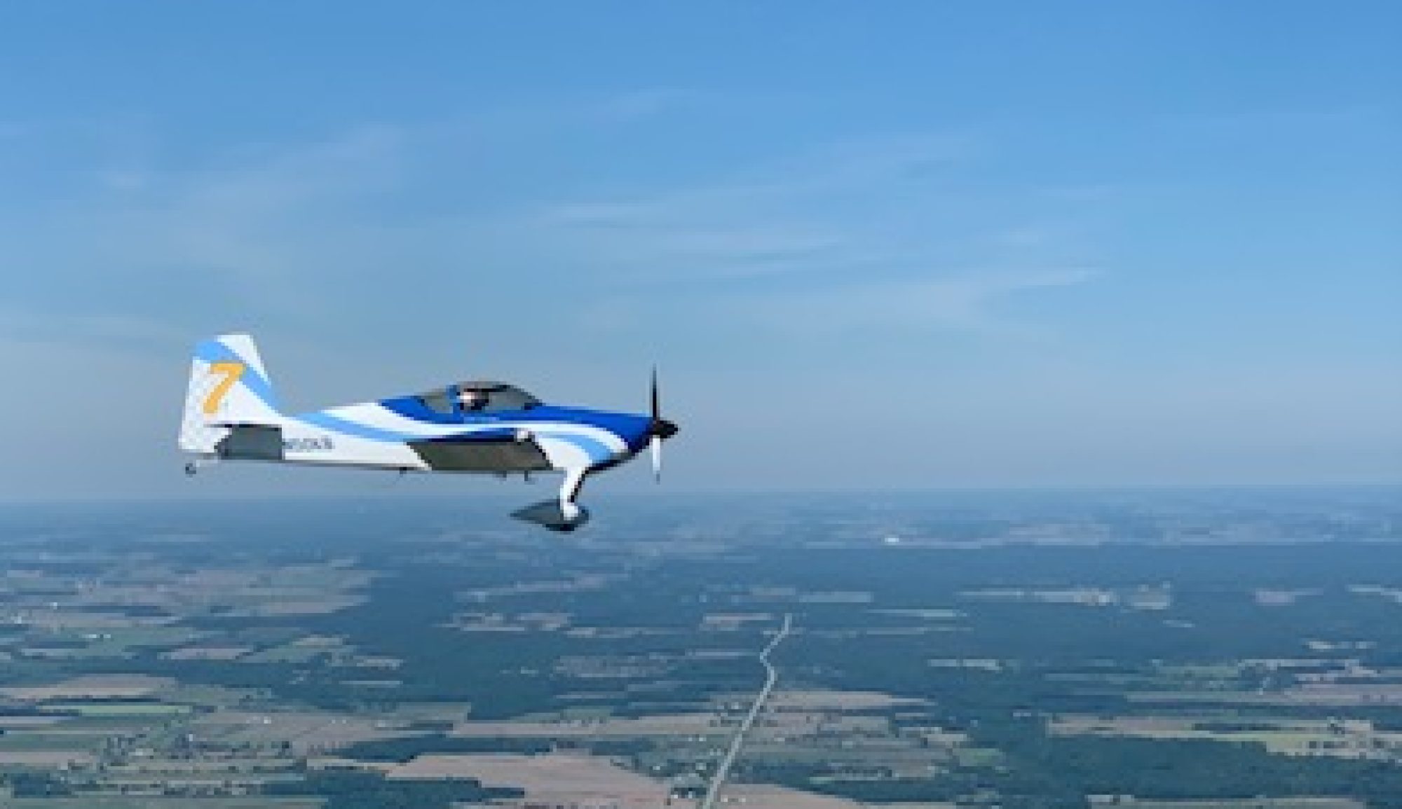
Soon after the wings were mounted the FAA approved a Registration Certificate for Vans RV7 N50KB, known to us as “The Dream Weaver”. That didn’t reduce the number of tasks yet to be accomplished. I next
- installed gussets connecting the fuselage side skins to the wing main spar. Two of the 1/4″ bolts were too short and were replaced by Vans.
- Installed the 22 #8 screws that attach the lower wing skins to the fuselage bottom skin
- Bolted the wing rear spars to the center rear spars. This required removing and reinstalling the flaps. Flap push-rod lengths were adjusted to synchronize the two flaps.
- Connected aileron push-rods to the center section controls
- Installed the outside air temperature probe onto a right wing inspection plate
- Confirmed the angle between the wing top skin and the flap top skins are 45 degrees when in the down position
- Identified, tested, labeled and prepared the 28 wing light wires for connection to a terminal strip under the PAX seat. The LED landing lights draw 13.3 amps and were assigned a 15 amp breaker in the VPX Pro electronic breaker box.

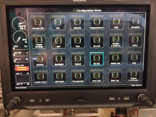
- Worked through the Garmin menu structure to find the VPX control page on the MFD screen.

- Then connected the VPX box’s serial port to my laptop computer and configured the breaker ratings for each circuit.
- Set the graphical image colors and limits for the Garmin screen’s graphical flap, fuel, and trim position indicators.
- Threaded the pitot and AOA tubes up from the left wing root through the armrest support and on to the instrument sub panel where they were connected to the #1 and #2 ADAHRS units.
[KGVID]http://bambas.com/wordpress/wp-content/uploads/2018/03/Stick-Movement.mp4[/KGVID]
- Filmed the ease of flight control movement.
- Installed fuel lines between the wing tanks and the fuselage manifold.
Then it became time to do the inspection required by the newly announced Lycoming Service Bulletin #632.

