Lycoming Service Bulletin No.632

While we were in Oshkosh, WI for the annual EAA convention, Lycoming announced a manditory service bulletin for about 1300 engines that had been manufactured in 2016, plus all engines that had been overhauled with new piston rods around that time.  Our engine serial number was one of those listed.  The inspection involved purchasing and using a special tool to find those connecting rods that may have looser than specified bearings in their upper ends.

An FAA Airworthiness Inspector friend who once owned an aircraft engine overhaul shop helped me get the job done.
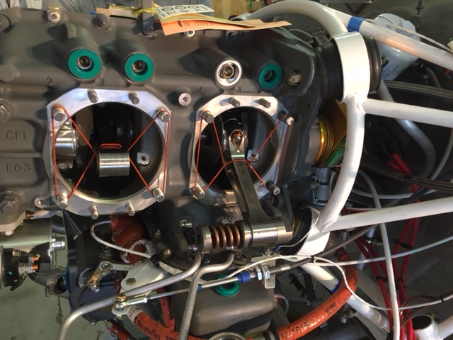
Lycoming S/B 632 Inspection

The photo shows the tool (a big coil spring attached to the #4 cylinder’s rod.  If the bearing starts to slide out when the spring is compressed by six turns of its inner bolt, it fails.  We were lucky all four rods passed.  Note the red cylinder base o-rings that are used to keep the connecting rods from flopping around during the disassembly. The S/B was just a PITA that slowed progress by three days.

August 10 to August 29, 2017

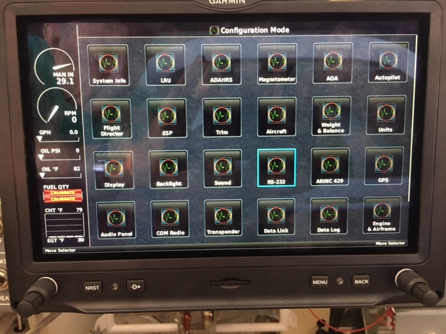
The Garmin G3X Touch Configuration Menu starts here

Soon after the wings were mounted the FAA approved a Registration Certificate for Vans RV7 N50KB, known to us as “The Dream Weaver”.   That didn’t reduce the number of tasks yet to be accomplished.  I next

  • installed gussets connecting the fuselage side skins to the wing main spar. Two of the 1/4″ bolts were too short and were replaced by Vans.
  • Installed the 22 #8 screws that attach the lower wing skins to the fuselage bottom skin
  • Bolted the wing rear spars to the center rear spars.  This required removing and reinstalling the flaps.  Flap push-rod lengths were adjusted to synchronize the two flaps.
  • Connected aileron push-rods to the center section controls
  • Installed the outside air temperature probe onto a right wing inspection plate
  • Confirmed the angle between the wing top skin and the flap top skins are 45 degrees when in the down position
  • Identified, tested, labeled and prepared the 28 wing light wires for connection to a terminal strip under the PAX seat.  The LED landing lights draw 13.3 amps and were assigned a 15 amp breaker in the VPX Pro electronic breaker box.
  • Worked through the Garmin menu structure to find the VPX control page on the MFD screen. 
  • Then connected the VPX box’s serial port to my laptop computer and configured the breaker ratings for each circuit.

    A VPX Pro Configuration Screen on a Laptop Computer
  • Set the graphical image colors and limits for the Garmin screen’s graphical flap, fuel, and trim position indicators.
  • Threaded the pitot and AOA tubes up from the left wing root through the armrest support and on to the instrument sub panel where they were connected to the #1 and #2 ADAHRS units.

[KGVID]http://bambas.com/wordpress/wp-content/uploads/2018/03/Stick-Movement.mp4[/KGVID]

  • Filmed the ease of flight control movement.
  • Installed fuel lines between the wing tanks and the fuselage manifold.

Then it became time to do the inspection required by the newly announced Lycoming Service Bulletin #632.

The Flightless Bird Grows Wings

Waiting for Wings

For over a year, the wings have sat in their cradle waiting for this day.  Working on the fuselage was easier without the wings attached.  The day came when the next step in wiring was to connect the wing mounted taxi, landing, navigation and recognition lights.

I asked several RV friends to help Dolly and I with the job.

Getting Ready

Word spread around the airport and a gaggle of help arrived.  Knowing I would be in the cockpit driving close fitting bolts connecting the wings to the center section, I told everyone that Dolly was the floor manager for the operation.  She had helped when we did the test fit of the wings a year earlier.

Before mounting the wings, we sorted out the coils of lighting wires and fed them into the fuselage.  We started with the left wing.  Both wings had been laid out on padded sawhorses next to the plane.  This was for safety in case we had to halt the process mid-way to completion.

In 2016 the wings were test fit and retained with lubricated drift pins that I had made from hardware store bolts in a mini-lathe.  Now for each wing, two drift pins were driven in bolt holes before driving the first close tolerance bolt.  The pins provide initial alignment and are then replaced by bolts. 

There are a total of eight 7/16″ and eight 1/4″ close tolerance bolts holding the wings to the fuselage center section main spar.  They give one confidence in this aerobatic airplane.


When the wings were on we all enjoyed a great lunch of Subway sandwiches and cool drinks that Dolly had laid out. 

All in all, it was a great day!